https://thetuningschool.com/blogs/news.atomThe Tuning School - News2024-10-22T14:16:10-04:00The Tuning Schoolhttps://thetuningschool.com/blogs/news/the-atlas-boost-controller2024-10-22T14:16:10-04:002024-10-22T14:24:50-04:00The Atlas Boost ControllerBrandon Thomas
The ATLAS Boost Controller for Positive Displacement Superchargers from The Tuning School.
Experience seamless transitions, along with responsive and effortless drivability, using the MAP sensor to provide an even and consistent power delivery without sudden surges.
Take control of your boost with this fully electronic, revolutionary controller and place your order today.
Watch below for a review from our friends at Scoggin-Dickey Parts Center!
]]>
https://thetuningschool.com/blogs/news/mpvi3-101-tips-to-start-tuning-with-your-mpvi3-unit2024-10-08T09:24:48-04:002024-10-09T10:31:16-04:00MPVI3 101: Tips to Start Tuning With Your MPVI3 UnitBrandon Thomas
Video Transcript:
Bob Morreale here with The Tuning School and today I'm going to give you three things you need to know about the HP Tuners MPVI3 to get you started.
Number one is going to be, your MPVI3 unit actually stores your credits here inside the unit. What does that really mean? Well let's just say you've tuned a couple cars and maybe you need to change laptops. So, how does that work? It's actually really simple. You can actually use any laptop you want. You can use your buddy's laptop. The credits don't reside on the laptop they actually reside and they're stored in the memory chip here.
So all you have to do is get your software installed on the new laptop, resync the device, and then boom, you're up and running, good to go. Which is actually really good for you.
Number two, what do I do if this is destroyed? We hear it all the time. Sometimes people will literally run it over with a car by accident. Sometimes, somebody steals it and you just don't know. But here's the thing guys, this is what a lot of shop owners and tuners overlook. This is one of those tools in your toolbox that actually goes up in value over time.
So, because of those things that I said could potentially happen to you, you need to have your shop insurance aware of that, so that they know. Maybe once a year or twice a year you call them and you say hey this tool that I have has gone up in value by this amount of dollars, because I've added this many credits to it. If it's ever lost or stolen they'll actually replace it for their proper value or at least they should. But one little tip, if you are ever in that situation, because sometimes it falls on the floor and it gets run over by a car. I've seen it plenty of times. Save it, put it all, all little pieces in a Ziploc bag and then let HP tuners know and usually what they could do is assemble it enough to at least know that you are legitimate and you have your device and it was destroyed. And with the purchase of a new device, I've seen them actually transfer your credits to the new device. It’s a good thing, just keep it if you can. If it's stolen, that’s a totally separate issue between you and your insurance company.
And then number three, how do I get my wideband data into my HP tuners unit? Because, this is a common thing every tuner has to know how to do. So, I've got a wideband here. This is an AEM unit and there's two different ways of getting your data into your HP tuners unit.
The first and most common way for all of your 2008 and newer vehicles is going to be to use the canbus plug that comes with your wideband. It literally plugs in line here between the unit and the car. Super simple, easy setup. At The Tuning School we've got a lot of great videos on how to do that.
But, let's say option two is your only bet. Maybe you've got a 2007 or older vehicle. Well you're going to need a way to get that data out of this wideband and into your HP tuners unit. If you have an MPVI3 you're going to need what's called the ProLink+. The ProLink+ literally plugs right into the M8 connector, which is a motorsports connector, right here on the front of the unit. And then the other end of it goes into the wideband's output, which is called analog output. There's a ton of wires here, but honestly there's only really two you need to worry about. One's going to be a ground wire and the other one is going to be a signal wire, that comes out of the wideband goes into the ProLink+, then ultimately makes its way into the HP tuners unit. And from there to within the software.
We also have a bunch of great videos for that which is called analog input, on how to get your wideband into your HP tuners unit. So that's all I have for today, thanks for watching, stay tuned.
Check out the video below for how to set the wideband up in the scanner.
]]>
https://thetuningschool.com/blogs/news/top-5-tuning-tips2024-09-16T15:44:31-04:002024-09-16T15:44:31-04:00Top 5 Tuning TipsBrandon Thomas
TRANSCRIPT:
Hey guys, it's Bob Morreale here with The Tuning School and I'm going to give you five tips to help you when you're tuning so let's go ahead and get started.
Number one, best tip I can give you is going to be, know your customer. So what does that really mean? When the customer comes in with the vehicle, do a good job of looking it over and putting it to paper. So ,when students come through our classes one of the biggest things I teach them is always write down what the customer tells you so is it a built. Is it high compression? What spark plugs are in it? What fuels are in it? What's the build look like? Is it something that sounds like it's going to work well together? Or is it something like maybe a really high compression engine with a supercharger on pump gas?
If you're a good tuner you're going to look for that and go uh hang on a minute I got to pay some particularly close attention to things like spark advance so I don't have a pile of pistons on the floor to clean up when I'm done.
So, number one best tip I can tell you is, know your customer, write it down and understand what you're tuning for as a good tuner that's so so important I can't stress that enough.
Number two, kind of similar: know the use of the vehicle. For example, if a customer comes in and says, "Hey, this is a drag race-only car. It never sees any other activity than drag strip competition. I want every horsepower you can give me." He's going to get a different tune than a customer who is maybe going to have mixed use. So, he doesn't need all of that. Maybe it's a vehicle that spends most of its time on the street, with some performance on the strip, and he just wants to optimize it. In that case, it won't get nearly as hot of a tune; it won't be nearly as on the edge as that full-blown drag strip-only car. So, it's very important to understand the use.
Then, I'm going to add on to that by saying: think about the worst-case scenario for that customer. Where do they live? Are there a lot of mountains they drive through? Is there going to be a lot of extra load on that engine? When you really understand this—and we talk about this on the dyno with our students in class—you have an ideal scenario here: the vehicle is on flat ground, it's a controlled environment, you're at the laptop making sure nothing is going wrong. But when you send that car down the road, you want to make sure that you didn't send it out on the edge and that you've tuned for the worst possible situation.
Let's say you're tuning a truck, maybe a Silverado, and you're not getting any knock, and you've maximized the spark and are making great power. But at the end, the customer tells you, "Hey, by the way, I tow a 5,000-lb trailer every day." Well, that's actually your fault. You should have listened and asked upfront, "How do you use this vehicle?" When you tune for it, if you have a good load-bearing dyno, you're going to tell that dyno, "I want you to add enough load to simulate that 5,000-lb trailer." So that when he leaves and hitches that thing up, in the worst-case scenario, your tune is still good. It doesn’t knock, it's not lean, and there are no problems. You've done it right by the customer.
So those are two super important things. Number three is knowing your fuel. Is the customer always going to run the fuel that you are tuning on today? Maybe you've got 93 in the tank today, but are they always going to run 93? You need to find that out. Also, know the fuel in the context of the vehicle's use. Maybe it's a street-strip vehicle, and sometimes it sees use at the strip. What is the customer going to do? Well, if you tuned it on 93 and the customer, when he gets to the drag strip, is going to put C16 in, there's a problem. We talk about this in class quite a bit. You need to tune for the fuel. So, when the customer leaves, you've got to let them know, "Hey buddy, this is tuned for 93 octane, not C16," which is like 117+ octane. This means it's probably going to burn slower and make less power, so you should have tuned for that fuel to optimize the power. There’s nothing wrong with the fuel—it just has to do with the tune, and the fact that you need to tune for the specific fuel.
Okay, next one. Number four. You see this pile of laptops here? You’ve probably been wondering this whole time, "What is this?" Well, I'm going to ask you guys: what do all of these laptops have in common, other than the fact that they've been my laptops over the years? They're plastic. You hear this? They're crap. Yes, I've bought some crappy $200–$300 laptops over the years. They have worked fine, don't get me wrong, but number four, when I say number four, means: buy a good laptop. If you're going to be tuning routinely, try and get one that has some rigidity to it, that isn't plastic like these. All these laptops here share one thing in common: they're plastic, and they all have a problem with the motherboard. Why do you think that is? The motherboard flexed over the years from me getting in and out of the car. Every time you do that, it twists, and over time, maybe after a year and a half to two years, the cheap plastic one will give out.
There are better ones that do have a kind of plastic shell, but they're rigid. So when I say "buy a good laptop," I'm talking physically—it can't be cheap or flimsy. It needs to withstand getting in and out of the car without flexing. That's a big deal. Also, I do see some guys on the internet saying, "Just get a cheap laptop. An i3 or some low-level processor is enough." Well, it is probably enough, but don't forget: your time tuning equals money. Time is money, and money is time. So buy a good laptop, especially if you're a professional. Get something really good, like an i7, so it runs quickly and you're not sitting around waiting for it to grind through tasks and software. It’s a pet peeve of mine, so: good laptop—absolutely number four.
Number five: know your value. What do I mean by that? Don't be the cheapest guy around. Know your value, because your time has value. Especially as you tune for a number of years and time goes on, you refine your craft and get better at it. I always tell students in class: specialize. Become the guy (or girl) in your town that people will drive 500 miles to see because you're the best at whatever you're passionate about. If you love Corvettes, go be the best Corvette tuner you can. Specialize, and get to know the ins and outs of that platform. When you're tuning on that platform, you can more easily determine, "Is that a tune problem, or is that a mechanical problem?" This approach serves your customers better, which relates back to knowing your value, because then you can charge a premium. This is where you want to be as a good tuner—you're spending your time becoming an expert on your platform.
So, that's all I have for you today. I hope you guys enjoyed this video, and as always, stay tuned!
]]>
https://thetuningschool.com/blogs/news/how-to-set-up-a-can-bus-wideband-in-hp-tuners-vcm-scanner2023-10-20T13:03:49-04:002023-10-20T13:03:49-04:00How to Set Up a CAN bus Wideband in HP Tuners VCM ScannerBrett Lundquist
Setting up a CAN bus device such as a wideband in the VCM Scanner is very simple. However this is a common question we receive. To help you better understand, walk through these steps or watch the video above.
1. Any good CAN bus device comes with an OBD2 cable with a male and female end. This allows MPVI device to plug into the OBD2 port simultaneously. Ensure that your CAN bus cable is plugged in and your MPVI device is also plugged in.
2. Turn the key on and check for communication. This will prompt the VCM Scanner to search for modules and channels on the CAN bus network and allow you to select these items from the channels list.
3. Click on the Add channel near the top of your channel list.
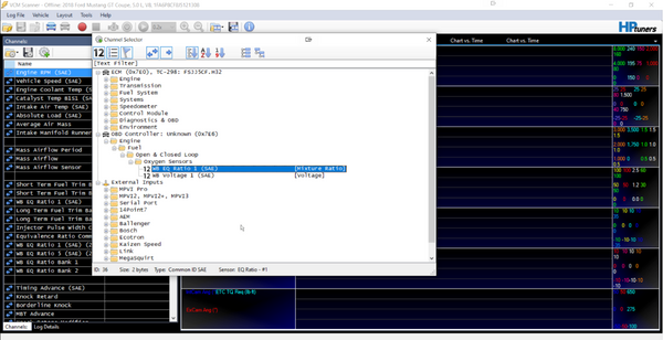
4. With the channels dialog box open, you will see an OBD Controller section. This is because the VCM Scanner identified this as another CAN bus controller on the network and pulled it into the list automatically. Expand this OBD Controller as you see below.
5. In our example, you can see we can choose between WB EQ Ratio 1 (SAE) and WB Voltage 1 (SAE). We want the WB EQ Ratio 1 for most situations. Double click on this to add it to your channel list.
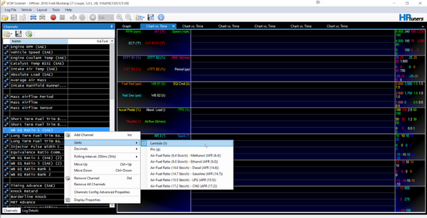
6. Lastly, you can choose the units you want this item to be displayed in. Right click on the new channel for WB EQ Ratio 1 (or whatever your device may be named) and then click on units. This will allow you to choose the units being recorded.
7. That’s all you need to do. Now when you begin recording the datalog, the channel will automatically record the CAN bus sensor into your datalog. There are no formulas or wires to set up. It’s plug and play!
]]>
https://thetuningschool.com/blogs/news/testing-and-tuning-with-the-ballenger-afr500c-wideband2023-10-09T10:34:27-04:002023-10-09T12:43:08-04:00Testing and Tuning with the Ballenger AFR500C WidebandBob MorrealeMany times, people are so excited to get started with a new project that they skip some basic, fundamental steps to ensure the output of their hard work is accurate and efficient. When using any wideband system, we always do a few quick checks first.
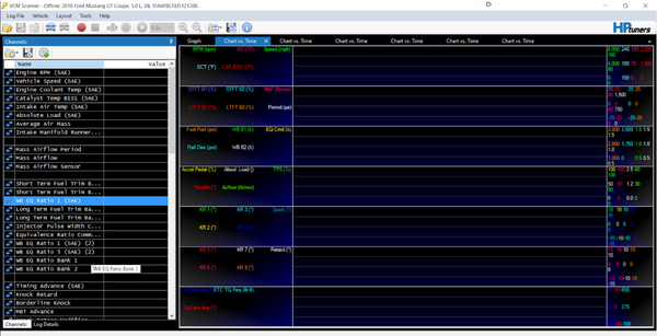
Set up your wideband correctly in the HP Tuners VCM Scanner channels (for setup watch this video). From the example below - we see the wideband showing in the channels list (left hand column, blue highlight) while the vehicle is at idle. The supercharged vehicle (2006 Corvette) we used was idling at 14.64:1 at the time, and the way we confirm the wideband is reading correctly is simple. We look at the narrowband O2 sensors (4th Group down, blue and purple oscillating lines). If the air/fuel ratio is stoich (typically 14.7:1) the sensors will oscillate. This matches the wideband (14.64:1), so we know the wideband is reading correctly at this point.
With this information in mind, we can now proceed with the full throttle testing sample for this article. Please keep in mind that this is not a comprehensive guide, but rather just a quick sample to show you how the process of full throttle tuning with a wideband typically works.
We always recommend that if you are just getting started, your WOT spark advance and commanded Air/Fuel ratio to a safe number. Those values will vary with the fuel, compression ratio, boost levels, etc… that your vehicle was built with.
With our example - the supercharged 2006 Corvette, we commanded an Air/Fuel ratio of 11.5:1 (with gasoline that we were running at the time).
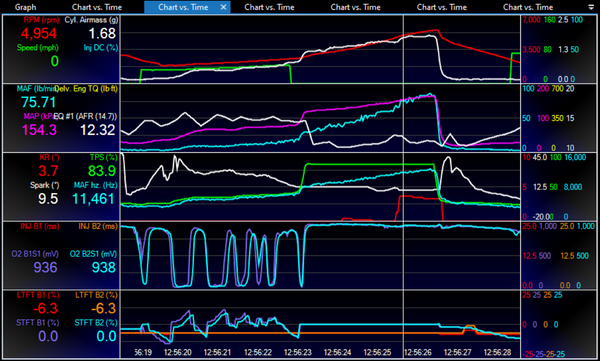
After setting those parameters in the tune and uploading, we moved on to the actual test. Below is a sample from the dyno pull we did - showing several obvious issues - but hey, this is real life and makes for great examples to learn from.
Reading this scan from top to bottom, we see a few things straight away that the wideband has revealed to us. At 4,954 RPM during the pull, we went a good bit leaner than our commanded 11.5:1 AFR. At 12.32:1 AFR, thats almost a full point leaner than commanded. This created a domino effect, causing knock (see the KR (red) line, 3rd group down) of 3.7 degrees.
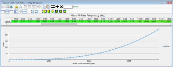
Having the wideband giving us good data is critical to finding and fixing the issue. As we highlight in the video, most ECM’s operate on a MAF based or Speed Density (MAP) based system. We teach a comprehensive process with our GM LS HP Tuners Printed and Online courses, giving you the exact details. However, for our purposes here - look below for a sneak peek at the process.
After we've located the before and after area of the lean spot, we realized the problem could be fixed by increasing the Mass Airflow table values from 10,700-11,700 hz. We determined that by looking at the scan (see the video) of the lean spot’s before and after areas.
Adjusting this table upward will increase the fuel the ECM commands for that range, thus resolving our lean spot.
The same basic steps are used in a Speed Density system, whether standard (GM GEN III) or Virtual VE (GM GEN IV), as shown in the video.
As you can see, having a good quality Wideband is critical for any tuner or calibrator to make informed decisions, and proper revisions to test. Typically after following this process the issue can be resolved within a few uploads, resulting in a smooth commanded and actual Air/Fuel ratio, and a resolution of any knock retard - which as you can guess - is the goal of any good tuner!
]]>
https://thetuningschool.com/blogs/news/how-to-setup-your-ballenger-wideband-in-hp-tuners-vcm-scanner2023-08-29T11:01:48-04:002023-08-29T11:41:39-04:00How to Setup Your Ballenger Wideband in HP Tuners VCM ScannerBob Morreale
Now that you have completed the process of physically installing the wideband sensor into either a new o2 Bung, a secondary o2 sensor location, or in the tailpipe it’s time to move on to setting up the analog output or CAN bus to work with your HP Tuners VCM Scanner or software of your choice.
Before we do…Here’s a Pro-Tip - Wait to power up your new wideband until after you finish setup with the scanner software. The wideband’s heater circuit draws a large amount of power from the vehicle’s battery, so don’t leave the key on for more than a minute without the engine running.
Analog Output vs CAN bus - which method do you need to use?
There’s just a few quick and simple factors to help you decide which way to get your data from the wideband into the VCM Scanner, or your favorite scanning/datalogging software.
Is the vehicle built after 2007? If so, most are CAN bus equipped and it will be easier to set up choosing this method.
Is the scanner you are using set up to work with CAN bus? (like HP Tuners VCM Scanner is) If so, CAN bus is an easy setup with no offset errors.
If the vehicle has CAN bus issues, or you are unsure if it is supported with your scanner, then Analog output is the way to go. This is typical for swap vehicles, older vehicles, standalone EFI Systems, etc…
]]>
https://thetuningschool.com/blogs/news/ballenger-part-12023-08-22T09:21:23-04:002023-08-22T09:37:05-04:00Ballenger Part 1Bob Morreale
The Ballenger AFR500C Wideband comes as a complete, ready to use wideband system. You may be tempted to just get started plugging wires together and such, but we recommend looking at your vehicle as a whole first. Answer the following questions before you really get into the wires.
How do you plan to use the wideband on this vehicle? Is it permanent in the vehicle or are you tuning for a short period and then removing it? You will need to know these answers because they dictate how you will install the actual wideband sensor components. There are three possible options for installation.
The first option is typically used if you are planning a permanent installation (or you want the most precise readings possible and don’t mind welding an O2 bung into place). This requires welding the included O2 sensor bung into your exhaust. For best results, do not install this into a primary tube on your headers, but rather about 4-6” back from the merge collector. This will give a good sample of the cylinders on that bank. If you get too close to a primary tube, the wideband will actually show you individual cylinder readings, making tuning much harder.
Also, do not place the bung below the centerline of the exhaust pipe. This will avoid the problem of water condensing on the bottom of the exhaust pipe and then ruining the sensor.
The second option is typically used during a dyno tuning session or a drag strip run and is never a permanent solution. This option includes temporarily removing a secondary O2 sensor and replacing it with the wideband during the tuning session. This is the second best option to welding an O2 sensor bung into the vehicle, since it places the wideband close to the engine. The only drawback to this method is that if the vehicle is equipped with catalytic converters, the sensor may read a bit leaner than the engine is actually running due to the actions of the catalytic converter. This is not necessarily an issue, since the actual AFR of the engine will be slightly richer than you are reading. Typically there is less than half a point difference between the actual AFR at the engine and what is being read after the catalytic converter. While this is a popular method on most dyno tuning sessions, Dodge tuners have learned that unless compensating in the tune, removing a secondary O2 sensor for tuning can cause problems with incorrect fueling during the tuning session. Thus, most Dodge tuners know what to adjust in the tune in order to use a secondary sensor location, or they use another method.
The third option is also typically used during a dyno or drag strip tuning session. This method includes using a tailpipe exhaust clamp.
This option is the easiest of all to use, and is often used for a quick tune check or a dyno day pull. The upside of this option is that you can quickly install it on any vehicle and be up and running quickly - tuning or diagnosing. There are three drawbacks to this option that are apparent. The primary issue is a short delay or “lag” from when the airflow makes its way out of the engine and all the way back to the sensor at the tailipipe. Most tuners know this and compensate by simply adjusting their changes a little earlier. The secondary issue is that this also suffers from the same issue as using a secondary O2 sensor location (the catalytic converter’s action makes the sensor read a little leaner than the engine really is). The final issue related to using the wideband in the tailpipe is related to how it typically reads at idle and light throttle. On many vehicles, the sensor can read poorly until wide open throttle is applied, since the tailpipe creates an effect of drawing fresh air into the exhaust clamp at idle and light throttle conditions. Thus, we do not recommend any idle or part throttle tuning be done using a tailpipe clamp, only wide open throttle.
Lastly, after you have installed the system in your vehicle application, it’s time to move on to how you want to get the wideband’s data out from the wideband and into your favorite software.
When using the wideband on a carbureted vehicle, there isn’t really any data recording/logging typically done, unless you have a system just for that purpose. But if you do, you can use the analog outputs to get your data out from the wideband and into your Datalogger. Similarly, most aftermarket EFI systems and OEM level tuning software will accept analog Inputs and/or CANBUS from widebands. So, how does all this work? Stay tuned for our next article where we cover all of these questions in detail!
]]>
https://thetuningschool.com/blogs/news/checklist-before-leaving-for-your-dyno-testing2023-07-31T13:43:07-04:002023-07-31T13:43:08-04:00Checklist Before Leaving for Your Dyno TestingBrett Lundquist
Just a few things to remember to check before you head off to the dyno and test your vehicle. Go through this quick checklist to make sure you don't have to make multiple trips!
]]>
https://thetuningschool.com/blogs/news/calculating-injector-size2023-07-20T10:00:00-04:002023-07-20T12:56:15-04:00Calculating Injector SizeBrett Lundquist
Fuel injectors play a crucial role in delivering the precise amount of fuel to an engine's combustion chambers. Determining the correct injector size is vital for optimizing engine performance, ensuring proper fuel delivery, and achieving optimal fuel efficiency. This video will delve into the process of calculating injector size, providing you with the necessary information to make informed decisions when upgrading or replacing injectors.
Understanding Injector Flow Rate:
The flow rate of an injector is typically measured in pounds per hour (lb/hr) or cubic centimeters per minute (cc/min). It indicates the amount of fuel an injector can deliver within a given time frame. The injector size you need will depend on the engine's requirements, specifically its power output and the desired air-to-fuel ratio.
Step 1: Determine Engine Requirements:
Before calculating the injector size, you must assess your engine's requirements. Factors to consider include the desired horsepower, the type of fuel system (naturally aspirated or forced induction), the fuel pressure, and the desired air-to-fuel ratio. These parameters provide the foundation for calculating the injector size accurately.
Step 2: Calculate the Base Injector Flow Rate:
To calculate the base injector flow rate, you need to determine the engine's approximate fuel requirements. The general guideline is to multiply the desired horsepower by the Brake Specific Fuel Consumption (BSFC) rating for your engine.
BSFC is a measure of the fuel efficiency of an engine and is typically expressed in lb/hp/hr or g/kW/hr. Different types of engines have varying BSFC values, and factors such as fuel type and engine technology also influence it. For example, naturally aspirated gasoline engines generally have a BSFC of around 0.50 to 0.60 lb/hp/hr, while turbocharged engines may range from 0.60 to 0.65 lb/hp/hr.
Step 3: Consider Additional Factors:
The duty cycle is usually expressed as a percentage and represents the injector's on-time relative to its total cycle time. It is crucial to select an injector that can provide enough fuel flow at your desired duty cycle to avoid performance issues or premature injector failure. The maximum safe injector duty cycle is generally somewhere between 70-85%. Most tuners will settle around 80%. This would be at it’s maximum duty cycle, so we suggest up sizing slightly to avoid running constantly at the maximum duty cycle.
Fuel pressure affects the flow rate of injectors. Higher fuel pressure generally results in increased flow rates, while lower pressure reduces them. It is important to account for the actual fuel pressure at which the injectors will operate and adjust the calculations accordingly.
Injector latency, or dead time, refers to the time delay between the injector receiving an electrical signal and actually opening. This delay affects fuel delivery accuracy. You may need to consult manufacturer data or conduct tests to determine the injector latency for precise calculations.
Step 5: Select the Appropriate Injector:
Once you have the adjusted injector flow rate, you can select an injector with a flow rate closest to that value. Manufacturers provide injector flow rate data, allowing you to choose the right size from their product offerings.
Conclusion:
Calculating the correct injector size is essential for optimizing engine performance, ensuring proper fuel delivery, and achieving the desired air-to-fuel ratio. By understanding your engine's requirements and following the step-by-step process outlined in this guide, you can accurately determine the injector size needed for your specific application. Remember to consider additional factors such as duty cycle, fuel pressure, and injector latency to make an informed decision.
Calculate Injector Size Based On Desired Crank HP
Formula:
[(Crank HP Desired ÷ Maximum Injector Duty Cycle) x BSFC] ÷ Number of Injectors = Injector Size in #/hr
Example: [(500 ÷ 0.80) x 0.65] ÷ 8 = 50.78
Calculate the Potential Crank HP Based on Injector Size
Formula:
[(Injector Size in #/hr x Number of Injectors) ÷ BSFC] x Maximum Injector Duty Cycle = Estimated Crank HP
Example: [(50.78 x 8) ÷ 0.65] x 0.80 = 499.98
Injectors that The Tuning School Recommends LINK HERE
]]>
https://thetuningschool.com/blogs/news/how-many-credits-do-i-need2023-07-11T13:54:04-04:002023-07-13T14:20:36-04:00How Many Credits Do I Need?Brett Lundquist
How many HP Tuners credits do I need to flash my vehicle?
Have you had trouble figuring out how many HP Tuners credits you'll need to purchase to license a file? This short video will show you how to figure this out with a few easy to follow examples. Then you can hop over to the Tuning School's website and order those credits with confidence.
]]>
https://thetuningschool.com/blogs/news/the-aem-x-series-vs-ballenger-afr500-wideband2023-07-06T08:00:00-04:002023-07-06T08:00:00-04:00The AEM X-Series vs Ballenger AFR500 WidebandBob MorrealeIf ever there was a subject that was the cause of great debate, Wideband O2 sensors would be right at the top of that list. In fact, while writing this article I stopped and made a quick post on Facebook to ask my friend group (mostly experienced tuners and calibrators) what they thought of the AEM vs Ballenger widebands. Not surprisingly, I got back a wide range of answers supporting both brands, each with their own reasons and experiences, some of which I reference here. When deciding between these two brands, I found there are just a few important factors that distinguish between AEM and Ballenger Widebands, since both brands make excellent products.
Let’s start the discussion with the obvious -Price.
When comparing, the AEM X-Series comes in at just $258 (with CANBUS support, for vehicles built after 2007). This includes everything you need - a digital gauge, Wideband O2 sensor, OBD2 interface connector, and a built-in O2 controller inside the gauge. The plug and play kit put together by The Tuning School includes the cigarette lighter adapter so no wiring is necessary to power and use this in any vehicle you choose.
When pricinging the Ballenger, there are currently two versions I would consider. The AFR500 (priced at $364, no CANBUS) or the AFR500C which includes CANBUS support (for vehicles built after 2007) for an additional $100, making it $464. This also is a complete kit, provided by The Tuning School with a cigarette lighter adapter included to make it a plug and play solution. I would recommend the AFR500C if you ever plan to tune any vehicles made from 2007 and newer using HP Tuners, SCT or other OEM tuning solutions. If not, you can buy the AFR500 and just use Analog outputs for your favorite tuning software (also perfect for aftermarket EFI systems).
Both versions of the Ballenger are still very affordable, and given that neither brand is exceedingly expensive, we don’t see a need to eliminate one brand just based on price.
The next deciding factor isaccuracy and repeatability.
While AEM publishes this chart showing their system’s response times, Ballenger is not on this list. However, the consensus among our group of tuning experts is that the average tuner would not notice any discernible difference between the two brands during most tuning situations. Meaning, both systems would report the same AFR (within one decimal place) at the same time.
However, there is more of a debate regarding repeatability, where most tuners and calibrators I asked leaned towards the Ballenger - citing the superior electronics and sensors, with optional O2 sensors ranging from production grade to lab grade. The Ballenger is the closest unit you can buy to a full lab-grade unit without significantly increasing price (typically more than triple the cost of a Ballenger unit).
My opinion is that if you are an enthusiast or the average aftermarket performance shop tuning a modified vehicle, you probably aren’t too worried if your Wideband reports 11.70:1 vs 11.75:1… making this factor a wash between both brands. If you are more of the engineering and product development oriented company, or even a seasoned tuner who considers themselves more of a calibrator and you value the most accuracy and repeatability possible, you would typically lean toward the Ballenger, especially considering the added cost over the AEM is small.
The last factor - How do you plan to use it?
Usage and Quality Needs
AEM’s X-Series is very easy to move from vehicle to vehicle, or even permanently mount to your favorite vehicle in a gauge pod. As such, it is a favorite for many tuners. The CANBUS feature is easy to integrate into your favorite tuning software, such as HP Tuners or SCT. The quality is great and it has a great range of operation that supports most tuning needs - including Gasoline, E85 and more. The range of the AEM display is 8.0:1 - 20.0:1 AFR for Gasoline, 5.7:1 - 12.0:1 (E85 tuning) and 0.55 - 2.0 Lambda, for tuners who prefer using Lambda. It has multiple analog outputs (0-5V), to input into HP Tuners Pro Link or any other software with Analog inputs, including Aftermarket EFI systems. Most of the tuners I discussed this unit with had no problems and enjoyed it’s low entry cost and CANBUS use, and portability. For the low entry price, it’s a great unit with a lot of features.
Ballenger’s AFR500 is also easy to move from vehicle to vehicle, but is not an ideal candidate for permanently mounting in a single vehicle. The electronics and lab grade sensors make this superior, according to most tuners I discussed this unit with. If you are considering a professional career in a performance shop or tuning environment, this would be a favorite. Durability, quality and performance are the hallmarks of this device, making it the go-to favorite for seasoned tuners and calibrators. It can easily be permanently installed with your favorite Dynamometer and also integrated with HP Tuners, SCT or any aftermarket EFI system, with either CANBUS or Analog outputs. The system is compatible with Gasoline, E85, Flex and all variations in between including Propane, CNG and more. It has multiple analog outputs (0-5V), to input into HP Tuners Pro Link or any other software with Analog inputs, including Aftermarket EFI systems.
In conclusion - the decision should not be made on price alone, since both are closely priced and inexpensive for the features they provide. I’d recommend looking at how portable or permanent you want your wideband to be, as well as your long term plan. Both units are portable, accurate and easy to use. Both are easily integrated with HP Tuners, SCT, Holley or any aftermarket system you desire. The choice depends largely on your preference for price, accuracy, repeatability and longevity.
]]>
https://thetuningschool.com/blogs/news/hp-tuners-mpvi3-features2022-11-09T11:02:40-05:002022-11-16T19:53:05-05:00HP Tuners MPVI3 FeaturesBrandon Thomas
In this Tech Tuesday, we answer your questions on the new HP Tuners MPVI3. We also explain what has changed and what stays the same.
]]>
https://thetuningschool.com/blogs/news/hp-tuners-compliance-and-emissions-training2022-10-05T10:35:50-04:002022-10-07T15:44:18-04:00HP Tuners Compliance and Emissions TrainingBrandon Thomas
HP Tuners has updated their software to 5.0. With this update comes a bit of parameter access training that is quick and simple.
With the release of the all new MPVI3 from HP Tuners, came the launch of the new VCM Suite 5.0.4 software update. Many longtime users will notice a few changes to their software, most notably user access to emission related DTC codes and switches.
In order to re-enable these functions within the software, users are required to take a free emissions test to receive an unlock code. But don’t worry, it’s not as scary as it sounds and it’s rather easy to complete. And we hear you, “why do I have to do this?”. Simply put, we need to stay ahead of what is happening within our industry. Hopefully with the help of SEMA and our local legislation, we can see the RPM Act pushed forward, so we can continue to enjoy our race cars.
Learn more about these new updates with Dion in this week’s video. And to learn more about the RPM Act and how you can help, visit sema.org and make your voice heard with millions of others like you! Also checkout Bob’s recap from SEMA’s visit to Washington DC.
]]>
https://thetuningschool.com/blogs/news/micd-up-at-nmca2022-05-31T15:07:41-04:002022-05-31T15:07:41-04:00Mic'd Up at NMCABrandon Thomas
In this "underground" video, join us for some behind-the-scenes banter as we attend NMCA Bradenton 2022.
]]>
https://thetuningschool.com/blogs/news/differences-of-ford-ecms2022-05-17T12:36:59-04:002022-05-17T12:37:01-04:00Differences of Ford ECMsBrandon Thomas
On this Tech Tuesday we join Bob and Dion in discussing the difference between Ford ECMs from 1996-present.
]]>
https://thetuningschool.com/blogs/news/5-parameters-to-check-after-your-run2022-05-02T16:08:14-04:002022-05-02T16:08:34-04:005 Parameters to Check After Your RunBrandon Thomas
In this Tech Tuesday, Bob discusses 5 parameters you should check in HP Tuners VCM Scanner after your run at the drag strip.
]]>
https://thetuningschool.com/blogs/news/unspoken-rules-of-the-track2022-04-19T11:20:41-04:002022-04-19T11:20:42-04:00Unspoken Rules of the TrackBrandon Thomas
On this Tech Tuesday, we spend some time at the track. Brett, talks to us about some "unspoken" rules while drag racing.
]]>
https://thetuningschool.com/blogs/news/drag-racing-safety-tips2022-04-05T09:43:29-04:002022-04-05T09:43:30-04:00Drag Racing Safety TipsBrandon Thomas
While out at NMCA Muscle Car Mayhem in Bradenton, FL we decided to film a few quick tips at the track. On this Tech Tuesday, join Brett and Dion as they address different safety elements for the track. Whether you are a beginner or a frequent flyer, these tips are sure to help.
]]>
https://thetuningschool.com/blogs/news/what-is-efi-tuning2022-03-21T12:53:29-04:002022-03-21T12:53:31-04:00What is EFI TuningBrandon Thomas
On this Tech Tuesday, Bob and Dion discuss the world of EFI tuning. Do you have issues wrapping your head around what this niche world is all about? We discuss a bit about what is possible in the EFI world.
]]>
https://thetuningschool.com/blogs/news/reviewing-your-datalog-before-going-to-the-track-with-hp-tuners2022-02-04T10:14:35-05:002022-02-04T10:14:36-05:00Reviewing Your Datalog Before Going to the Track with HP TunersBrandon Thomas
New to reading data logs in HP Tuners and getting ready to hit the track? On this week's Tech Tuesday learn how to review data logs and look at important channels to inspect before your next race.
]]>
https://thetuningschool.com/blogs/news/what-is-the-hp-tuners-rtd-and-tune-delivery-network2022-01-21T13:13:00-05:002022-01-21T13:13:02-05:00What is the HP Tuners RTD+ and Tune Delivery NetworkBrandon Thomas
What is the HP Tuners TDN app, and what is a RTD device? On this Tech Tuesday, learn what these new features are and how you can use them to improve your business model.
With the TDN, remote tuning just got easier and faster. Cloud based tuning is now easier to manage with the new TDN Android and iOS App.
Large volume shops needing a way to manage your customer tunes without interference? Learn what the RTD is and how you can use it in conjunction with the TDN App to help streamline your business.
]]>
https://thetuningschool.com/blogs/news/ecoboost-spark-blowout2022-01-11T14:57:31-05:002022-01-11T14:57:32-05:00EcoBoost Spark BlowoutBrandon Thomas
Do you experience spark blowout on your Ecoboost F150? If so, here is a quick Tech Tip to help you fix that issue.
]]>
https://thetuningschool.com/blogs/news/ecoboost-tuning-differences-f-150-vs-mustang2021-12-06T11:26:13-05:002021-12-06T11:26:14-05:00Ecoboost Tuning Differences: F-150 vs MustangBrandon Thomas
In this Tech Tuesday we discuss tuning differences between the Ford Ecoboost F-150 and Ecoboost Mustang.
]]>
https://thetuningschool.com/blogs/news/getting-started-with-mpvi2-pt-4-write2021-10-25T13:30:55-04:002021-10-25T13:30:56-04:00Getting Started With MPVI2+ Pt. 4 - WriteBrandon Thomas
In the fourth and final installment of Getting Started with MPVI2+ we are now writing to the vehicle. Learn more about the write process in the VCM Editor and get ready to make donuts in the parking lot.
For information on differences between the MPVI2 and MPVI2+ check out the HERE
]]>
https://thetuningschool.com/blogs/news/differences-between-hp-tuners-mpvi2-mpvi22021-10-20T11:43:05-04:002021-10-20T11:43:06-04:00Differences Between HP Tuners MPVI2 & MPVI2+Brandon ThomasThis was a recorded livestream webinar on August 24, 2021. It goes over the differences between the MPVI2 and new MPVI2+
]]>
https://thetuningschool.com/blogs/news/getting-started-with-mpvi2-pt-3-edit2021-10-13T15:47:15-04:002021-10-13T15:47:16-04:00Getting Started With MPVI2+ Pt 3 - EditBrandon ThomasIn this third installment of Getting Started with MPVI2+, we talk about the edit function. Learn some quick tips and tricks inside the editor and scanner applications in the HP Tuners VCM Suite.
]]>
https://thetuningschool.com/blogs/news/getting-start-with-hp-tuners-mpvi2-pt-2-read2021-10-01T13:12:53-04:002021-10-01T13:12:54-04:00Getting Start with HP Tuners MPVI2+ Pt 2 - ReadBrandon ThomasIn this episode, Bob shows how to read a file using the HP Tuners VCM Scanner and Editor.
Video Available October 5, 2021 at 7:00am EDT
]]>
https://thetuningschool.com/blogs/news/5-sema-hacks2021-09-28T12:44:30-04:002021-09-28T12:44:31-04:005 SEMA HacksBrandon Thomas
Following these shortcuts will help you have a better visit to the SEMA Show.
If you are last minute planning for 2021 or preparing for a future show, follow these 5 hacks to make planning easier!
2021 SEMA Show booth location #23719 in Central Hall
Hotel footage courtesy of Westgate Resorts.
]]>
https://thetuningschool.com/blogs/news/getting-started-with-hp-tuners-mpvi2-pt-1-connect2021-09-20T14:06:32-04:002021-09-20T14:06:33-04:00Getting Started with HP Tuners MPVI2+ Pt 1 - ConnectBrandon ThomasIn part one of the MPVI2+ series, Bob explains how to connect the HP Tuners MPVI2+ using the supplied cables along with setting up software. If you are looking for info on how to get started with HP Tuners, this series is for you!
]]>
https://thetuningschool.com/blogs/news/best-ls-swap-of-ls-fest-20212021-09-15T10:20:11-04:002021-09-15T10:20:11-04:00Best LS Swap of LS Fest 2021Brandon ThomasJoin Bob and the crew to see what their favorite builds were from LS Fest East 2021! Do you have a favorite build?