


Many times, people are so excited to get started with a new project that they skip some basic, fundamental steps to ensure the output of their hard work is accurate and efficient. When using any wideband system, we always do a few quick checks first.
Set up your wideband correctly in the HP Tuners VCM Scanner channels (for setup watch this video). From the example below - we see the wideband showing in the channels list (left hand column, blue highlight) while the vehicle is at idle. The supercharged vehicle (2006 Corvette) we used was idling at 14.64:1 at the time, and the way we confirm the wideband is reading correctly is simple. We look at the narrowband O2 sensors (4th Group down, blue and purple oscillating lines). If the air/fuel ratio is stoich (typically 14.7:1) the sensors will oscillate. This matches the wideband (14.64:1), so we know the wideband is reading correctly at this point.

With this information in mind, we can now proceed with the full throttle testing sample for this article. Please keep in mind that this is not a comprehensive guide, but rather just a quick sample to show you how the process of full throttle tuning with a wideband typically works.
We always recommend that if you are just getting started, your WOT spark advance and commanded Air/Fuel ratio to a safe number. Those values will vary with the fuel, compression ratio, boost levels, etc… that your vehicle was built with.
With our example - the supercharged 2006 Corvette, we commanded an Air/Fuel ratio of 11.5:1 (with gasoline that we were running at the time).
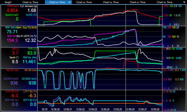
After setting those parameters in the tune and uploading, we moved on to the actual test. Below is a sample from the dyno pull we did - showing several obvious issues - but hey, this is real life and makes for great examples to learn from.
Reading this scan from top to bottom, we see a few things straight away that the wideband has revealed to us. At 4,954 RPM during the pull, we went a good bit leaner than our commanded 11.5:1 AFR. At 12.32:1 AFR, thats almost a full point leaner than commanded. This created a domino effect, causing knock (see the KR (red) line, 3rd group down) of 3.7 degrees.
Having the wideband giving us good data is critical to finding and fixing the issue. As we highlight in the video, most ECM’s operate on a MAF based or Speed Density (MAP) based system. We teach a comprehensive process with our GM LS HP Tuners Printed and Online courses, giving you the exact details. However, for our purposes here - look below for a sneak peek at the process.
After we've located the before and after area of the lean spot, we realized the problem could be fixed by increasing the Mass Airflow table values from 10,700-11,700 hz. We determined that by looking at the scan (see the video) of the lean spot’s before and after areas.
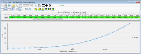
Adjusting this table upward will increase the fuel the ECM commands for that range, thus resolving our lean spot.
The same basic steps are used in a Speed Density system, whether standard (GM GEN III) or Virtual VE (GM GEN IV), as shown in the video.
As you can see, having a good quality Wideband is critical for any tuner or calibrator to make informed decisions, and proper revisions to test. Typically after following this process the issue can be resolved within a few uploads, resulting in a smooth commanded and actual Air/Fuel ratio, and a resolution of any knock retard - which as you can guess - is the goal of any good tuner!
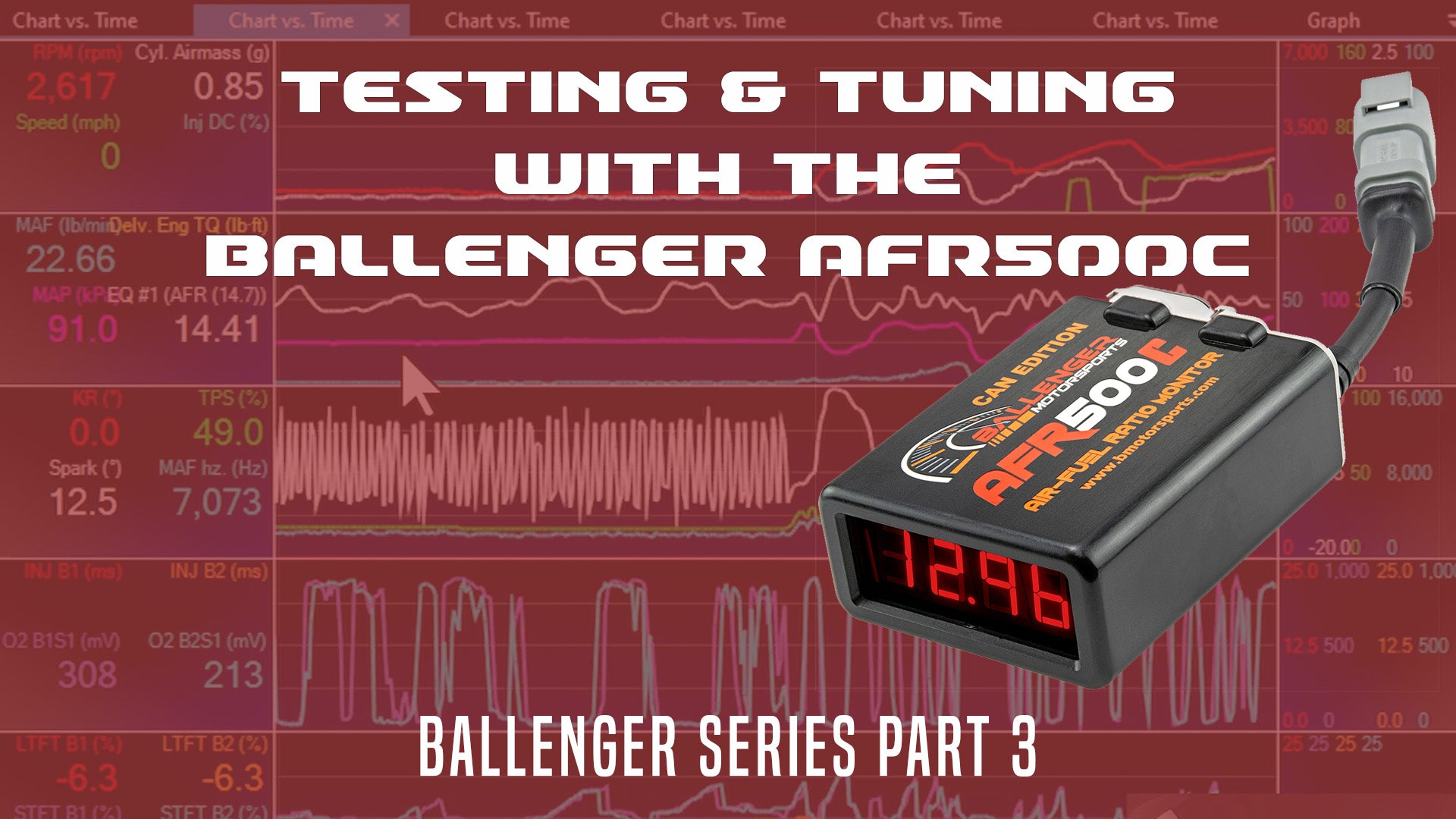
Ballenger Wideband AFR500CAN
Ballenger Wideband AFR500v2
Ballenger Series Part 1
Ballenger Series Part 2